The main objective of this week's project is to work out our own design with Simulink on MATLAB. First, in order to complete the aim, we learnt from an example that supervisor gave us as reference. The example power system circuit including relevant parameters is shown as follow in figure 1:
Figure 1
In addition, the whole calculation of three phase fault in this system is as follow in figure 2:.
Figure 2
Based on the design of example as well as our supervisor's advice, we set out designing our initial circuit, which is shown as follow in figure 3:
Figure 3
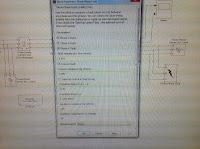
Screenshots below are the specific parameters setting for above circuit:
 |
| RLC Load1 |
 |
| RLC branch |
Simulink the system, the measurement of V and I are displayed using "scope", which is shown as follow in figure 4:
 |
| Figure 4 |
Notes we took the three phase fault as example. So when the fault occurs in the balanced system at an specific time, the voltage will decrease to 0 instantly and the fault current will increase immediately within transient time, which is set to be from 9.8s to 9.85s in our project.
It is clear that the whole system can run but result figure is not expected, which means that the connection of circuit is relatively correct but the parameters setting for any component may be incorrect.
In the whole, the objective of the project in this week was achieved successfully. However toward the problem we finally met, in next week it is highly recommended that we should amend and determine the final power system circuit design including calculation and setting of all parameters of components and then obtain simulation results in four types of power system faults, which were mentioned in week 1 blog.


没有评论:
发表评论