This week is the first week of our project, so we mainly did some preparation work. We met with our supervisor discussing how to start the project. Following supervisor's proposal, we decided to divide the whole project into three parts: First we ought to go through the relevant background knowledge related to power system fault, which is planed to end in week 1. In the second part, we are going to design the initial model of power system with Simulink function of MATLAB software and obtain the simulation figure, which is planed to last 3 weeks. In last week, we will do some calculation according relevant parameters to check whether the calculated result and simulation figure match.

In this week, we reviewed the lecture notes in module 209: "Power system", which mainly introduces the method of Symmetric Components and power system faults.
Symmetrical Component is a powerful technique for analysing unbalanced three phase systems under both normal and abnormal conditions. The key idea of symmetrical component analysis is to decompose the system into three sequence networks which are positive, negative and zero sequence respectively. The detail method is shown as follow in figure 1:

Figure 1
According to lecture note and other source from Internet, it can be summarized that there are mainly four types of power system faults:
- Single line-to-ground fault (SLG):A short circuit between one line and ground. The detailed solving solution is shown as follow in figure 2:

Figure 2
The connection of sequence networks for L-G fault is shown as follow in figure 3:

Figure 3
- Line-to-line fault(LL):A short circuit between lines. The detailed solving solution is shown as follow in figure 4:

Figure 4
- Double line-to-ground fault(DLG):Two lines come into contact with the ground. The detailed solving solution is shown as follow in figure 5:

Figure 5
- Line-to-line-to-line-ground fault:Three lines come into contact with the ground. The relevant graph is shown as follow in figure 6:
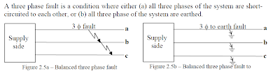

Figure 6
This is in general a balanced condition, and we need to only know the positive-sequence network to analyse faults. Further, the single line diagram can be used, as all three phases carry equal currents displaced by 120o.
Typically, only 5% of the initial faults in a power system, are three phase faults with or without earth. Of the unbalanced faults, 80 % are line-earth and 15% are double line faults with or without earth and which can often deteriorate to 3 phase fault. Broken conductor faults account for the rest.
Furthermore, the power system faulty still can be discussed from the symmetric components version, as shown in figure 7:

Figure 7
In addition to the lecture notes and Internet source, we still consulted some related books in library, the cover of one of those is shown as follow in figure 8:

Figure 8
Except for the power system fault analysis, Simulink with MATLAB is a vital part we went through as well:
MATLAB (matrix laboratory) is a high-level language and interactive environment for numerical computation, Developed by MathWorks, MATLAB allows matrix manipulations, plotting of functions and data, implementation of algorithms, creation of user interfaces, and interfacing with programs written in other languages, including C,C++, Java, and Fortran. An additional package, Simulink, adds graphical multi-domain simulation and Model-Based Design for dynamic and embedded systems.
Simulink, developed by MathWorks, is a data flow graphical programming language tool for modeling, simulating and analyzing multi-domain dynamic systems. Its primary interface is a graphical block diagramming tool and a customized set of block libraries. It offers tight integration with the rest of the MATLAB environment and can either drive MATLAB or be scripted from it.
Start with Simulink under MATLAB:
- Start MATLAB, then type "Simulink" in MATLAB work space. Simulink will open with Library Browser popped up, of which the library browser is used to build simulation models, shown in figure 9:

Figure 9
- Another way to open the library browser is to click "View" on the MATLAB toolbar, then click "Library Browser", shown as follow in figure 10:
.JPG)
Figure 10
- Next we needed to obtain the Simulink model, so click “File|New|Model” in the toolbar. An empty block diagram will pop up, shown as follow in figure 11:
.JPG)
Figure 11
- Model elements can be added by dragging the appropriate elements from the Library Browser into the model window. Alternately, the model element still could be copied from the Library Browser and pasted into the model window.
没有评论:
发表评论