2013年3月1日星期五

Week 5

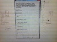
During the lab time of this week, a mistake was been found that we have not realized the conceptions between active power and reactive power. The given condition is that the rated power of the load impedance (Series R Load2)is 60MVA, but I have enter the value '60e3' to active power(Watt) by careless mistake. Thus, the calculated result is not agree with the simulated result. Then, the component settings have been checked and modified again. For convenience, the load has been regarded as a pure resistor with the voltage of 14.4kV and active power of 10MW. The nether figure can be recognized the modification directly.
Series R Load2(Modification)
Moreover, the improved circuit and the specific calculation process are shown below:
While, the measurement results of simulation have also been changed that are revealed in the following Figures.
No Fault
Vp = 10.5kV, Ip = 500A
Three Phase Fault
No Fault: Vp = 10.5kV, Ip = 500A

Fault value: Vp' = 0, Ip' = 3000A
According to the consequence of three phase fault simulation shown above, it is easy to see the calculated current value 537.4A(theory) is similar to the simulated current value 500A(experiment) under steady state. However, during the transient time, the calculated fault current value 5361.28A(theory) differs from the simulated fault current value 3000A(experiment). Therefore, the calculation for the actual fault current possibly has some mistakes and we did not work it out.
SLG Fault
No Fault: 
Vp = 10.5kV, Ip = 500A
Fault value(peak)
Va' = 0, Vb' = 10.5kV, Vc' = 10.5kV
Ia' = 3000A, Ib' = 500A, Ic' = 500A
LL Fault
No Fault: 
Vp = 10.5kV, Ip = 500A
Fault value(peak)
Va' = 10.5kV, Vb' = 0, Vc' = 5kV; 
Ia' = 500A, Ib' = 2000A, Ic' = 1500A
DLG Fault
No Fault: 
Vp = 10.5kV, Ip = 500A
Fault value(peak): 
Va' = 10.5kV, Vb' = 0, Vc' = 0; 
Ia' = 500A, Ib' = 2700A, Ic' = 2150A

What are we going to do next?
  • Find the mistake of fault current calculation
  • Design poster
  • prepare for the bench inspection (presentation, questions,etc.)
  • Start to work on the dissertation

2013年2月23日星期六

Week 4

It is only remaining one week to the end of this project. And the main objectives in this week is to simulate four types of fault occurring in the power system which are three-phase fault, single-line to ground fault, double line fault and double line to ground fault. 

Firstly, we have to design our own circuit for a simple power system which is demonstrated with specific physical values in the Figure 1 below. In addition, the base power and base voltage for this power system are regarded as 100 MVA, 154 kV respectively.

Then, the corresponding schematic of the power system can be built in the model of MATLAB (Figure 2) on the basis of the painted circuit above(Figure 1). 


Figure 2
The only difference between the two circuits above is that whether a fault is produced or not. In theory, the normal operation for a power system is either the three phase currents or three phase voltages all present steady alternating signals through the whole system. If a fault appears at a certain time, there will be an abnormal phenomenon with unstable current and voltage signals during the transition time.

Next step is the most significant part which is to set the properties for each element properly in terms of those given messages. Moreover, the nether screenshots are the exact settings for our  design.
  
Series RL Branch
 
Transformer 1
Source
          
Transformer 2
Series R Load
     
Three Phase Fault


After everything is ready, the simulation can be started. For the normal operation, the measurements for Vabc, Iabc are shown below:   
No Fault
Besides, the three phase fault is the primary pattern for consideration in this project. Since, the three phase short-circuit (to ground) fault belongs to the symmetrical fault, each phase is identical. And the Vabc would become 0(GND) immediately after the fault occurs, whereas  Iabc would increases rapidly towards a very large value during the transient time. As the simulation for three phase fault shown below, the theory can be verified by reality, so using MATLAB software to solve the power system fault is efficient and reliable.
Three Phase Fault
In the same way, the another three unsymmetrical short-circuit faults can also be simulated and the result of simulation is demonstrated below.
SLG Fault
LL Fault
DLG Fault

  • Calculations (Per-unit System - Three Phase Fault)


2013年2月15日星期五

Week 3


The main objective of this week's project is to work out our own design with Simulink on MATLAB.  First, in order to complete the aim, we learnt from an example that supervisor gave us as reference.  The example power system circuit including relevant parameters is shown as follow in figure 1:
Figure 1
In addition, the whole calculation of three phase fault in this system is as follow in figure 2:.
Figure 2

Based on the design of example as well as our supervisor's advice, we set out designing our initial circuit, which is shown as follow in figure 3:
Figure 3
Screenshots below are the specific parameters setting for above circuit:
RLC Load1

RLC branch


RLC Load
Three phase fault
powergui

Simulink the system, the measurement of V and I are displayed using "scope", which is shown as follow in figure 4:
Figure 4


Notes we took the three phase fault as example.  So when the fault occurs in the balanced system at an specific time, the voltage will decrease to 0 instantly and the fault current will increase immediately within transient time, which is set to be from 9.8s to 9.85s in our project. 
It is clear that the whole system can run but result figure is not expected, which means that the connection of circuit is relatively correct but the parameters setting for any component may be incorrect.
In the whole, the objective of the project in this week was achieved successfully.  However toward the problem we finally met, in next week it is highly recommended that we should amend and determine the final power system circuit design including calculation and setting of all parameters of components and then obtain simulation results in four types of power system faults, which were mentioned in week 1 blog. 


2013年2月8日星期五

Week 2

Last week, we had done some preparation work for our project, such as consulting some introductions, articles and reports which are related to power system fault analysis as well as the method of simulation by MATLAB. In this week, we set about designing the model of power system applying the simulink tool of MATLAB software. Owing to the provided demos of power system simulation, we can make more sense to what we are going to do. An example is shown below in the Figure 1,
Figure 1
but it is relatively more actual power system design with complicated components and connections compared to the requirement of our project. However, it is a useful case indeed provided for us to make a simplification. According to the complex demo, we took an attempt to design several circuits with some electrical components like three phase source, distributed parameters line, impedance, transformers and that sort of thing. One of our designs is demonstrated in the Figure 2.


Figure 2
For consideration of different faults, a three phase fault device  should be added into the circuits. Seen from the window at the bottom right corner, it is the property and setting of three phase fault component. 

  • Ticking all of the fault refers to the balanced three phase fault.  
  • Only ticking one of the A, B, C fault and 'Ground Fault' refers to the unbalanced single line to ground(SLG) fault. 
  • Only ticking two of the A, B, C faults means the unbalanced double line(LL) fault.
  • Ticking two of the A, B, C faults and 'Ground Fault' means the unbalanced double line to ground(DLG) fault.
During the process of building the circuit, one problem was appeared that how to set the value of several parameters for each components. In addition, we didn't have any idea about how to give a reasonable value for a power system.

Our supervisor gave us an simple example with particular values which can be regarded as references. Also the distributed parameters line is difficult to calculate the exact values, so our supervisor advise us using the 'three-phase series RLC branch' which is easy to figure out. Moreover, the transformer is always essential in a real power system. Besides, the synchronous generator and the asynchronous motor are suggested to be instead of simple source and load.


Based on the proposal from supervisor, the general designs after improvement are revealed in the following Figure 3,4,5. 


Figure 3

Figure 4

Figure 5
Since the property setting error, the result of simulation isn't like the desired waveform and we managed to achieve the goal bu debugging each parameter, but the consequent can make us satisfied.


2013年2月1日星期五

Week 1

This week is the first week of our project, so we mainly did some preparation work.  We met with our supervisor discussing how to start the project.  Following supervisor's proposal, we decided to divide the whole project into three parts: First we ought to go through the relevant background knowledge related to power system fault, which is planed to end in week 1.  In the second part, we are going to design the initial model of power system with Simulink function of MATLAB software and obtain the simulation figure, which is planed to last 3 weeks.  In last week, we will do some calculation according relevant parameters to check whether the calculated result and simulation figure match.


In this week, we reviewed the lecture notes in module 209: "Power system", which mainly introduces the method of Symmetric Components and power system faults.

Symmetrical Component is a powerful technique for analysing unbalanced three phase systems under both normal and abnormal conditions.  The key idea of symmetrical component analysis is to decompose the system into three sequence networks which are positive, negative and zero sequence respectively.  The detail method is shown as follow in figure 1:
Figure 1

According to lecture note and other source from Internet, it can be summarized that there are mainly four types of power system faults:
  • Single line-to-ground fault (SLG):A short circuit between one line and ground.  The detailed solving solution is shown as follow in figure 2:


Figure 2
The connection of sequence networks for L-G fault is shown as follow in figure 3:

Figure 3
  • Line-to-line fault(LL):A short circuit between lines.  The detailed solving solution is shown as follow in figure 4:

Figure 4
  • Double line-to-ground fault(DLG):Two lines come into contact with the ground.  The detailed solving solution is shown as follow in figure 5:
Figure 5
  • Line-to-line-to-line-ground fault:Three lines come into contact with the ground.  The relevant graph is shown as follow in figure 6:
Figure 6

This is in general a balanced condition, and we need to only know the positive-sequence network to analyse faults. Further, the single line diagram can be used, as all three phases carry equal currents displaced by 120o.


Typically, only 5% of the initial faults in a power system, are three phase faults with or without earth. Of the unbalanced faults, 80 % are line-earth and 15% are double line faults with or without earth and which can often deteriorate to 3 phase fault. Broken conductor faults account for the rest.
Furthermore, the power system faulty still can be discussed from the symmetric components version, as shown in figure 7:
Figure 7


In addition to the lecture notes and Internet source, we still consulted some related books in library, the cover of one of those is shown as follow in figure 8:
Figure 8


Except for the power system fault analysis, Simulink with MATLAB is a vital part we went through as well:

MATLAB (matrix laboratory) is a high-level language and interactive environment for numerical computation,  Developed by MathWorks, MATLAB allows matrix manipulations, plotting of functions and data, implementation of algorithms, creation of user interfaces, and interfacing with programs written in other languages, including C,C++, Java, and Fortran.  An additional package, Simulink, adds graphical multi-domain simulation and Model-Based Design for dynamic and embedded systems.

Simulink, developed by MathWorks, is a data flow graphical programming language tool for modeling, simulating and analyzing multi-domain dynamic systems. Its primary interface is a graphical block diagramming tool and a customized set of block libraries. It offers tight integration with the rest of the MATLAB environment and can either drive MATLAB or be scripted from it. 

Start with Simulink under MATLAB:

  • Start MATLAB, then type "Simulink" in MATLAB work space.  Simulink will open with Library Browser popped up, of which the library browser is used to build simulation models, shown in figure 9:
Figure 9

  • Another way to open the library browser is to click "View" on the MATLAB toolbar, then click "Library Browser", shown as follow in figure 10:
Figure 10

  • Next we needed to obtain the Simulink model, so click “File|New|Model” in the toolbar. An empty block diagram will pop up, shown as follow in figure 11:
Figure 11
  • Model elements can be added by dragging the appropriate elements from the Library Browser into the model window. Alternately, the model element still could be copied from the Library Browser and pasted into the model window.
Now, the aim in this week has been achieved successfully.  Next week, we will try to by choose the appropriate and design the model of power system.